Really getting in Touit: We take apart Zeiss’ new 32mm lens to get a closer look
posted Saturday, June 15, 2013 at 8:31 AM EDT

A couple of weeks ago I posted my impressions of the Zeiss 32mm Touit lens for NEX cameras, based on a copy loaned to me by Zeiss, USA. Now that we have our own copies I can be, shall we say, a bit more aggressive in examining the lens. Not to mention getting an opportunity to continue my string of aggressively bad pun titles (which Drew absolutely hates). But, hey, don’t blame me. I didn’t pick the name. I just do what has to be done. I have yet begun to pun.
Anyway, given that a lens with electronic autofocus and aperture control was something new in the Zeiss consumer lineup, Aaron and I couldn’t wait to take a look inside and see how things were put together. Once we got a look inside, we found there was more Touit than we expected (don’t say I didn’t warn you). The lens is put together solidly in typical Zeiss fashion.
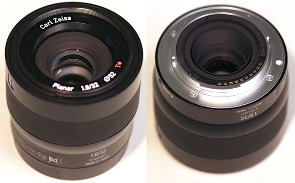
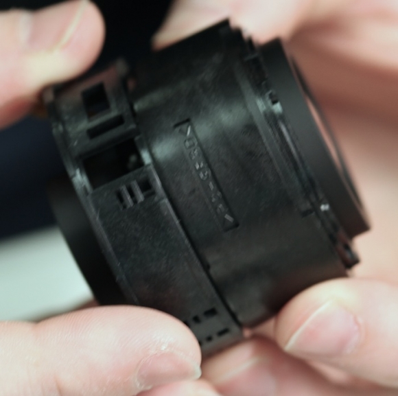
Outside examination of the 32mm Touit shows us the polymer barrel with metal mounting ring. Things appear solidly built and the focus ring, particularly, moves smoothly like a larger SLR lens (many mirrorless focus rings are loose and sloppy).
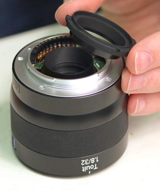
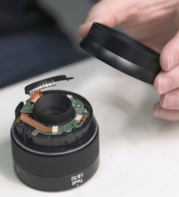
The rear light baffle is a separate piece mounted by three screws.
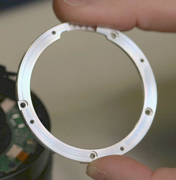
The rear mount then removes in the usual way. Underneath the rear mount is a thick metal shim or spacer.
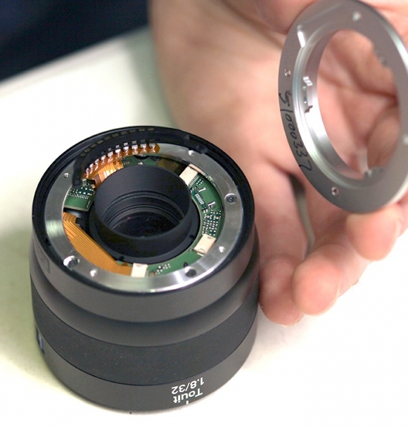
It seems rather thick to be a standard optical shim or adjustment for the difference in Fuji and Sony flange-to-sensor distances (which are only 0.3mm different), so I assume it is there for added structural rigidity.
With the spacer removed we can see the rear barrel of the lens is attached by three large screws and an additional two screws hold the rear PCB (circuit board) in place. This is typical sturdy Zeiss construction; the screws are longer and thicker than what you usually see in lenses of this size. At 10 o’clock you can see the silver cylinder of the DC motor peeking out from under the PCB, with the large flex connector from the PCB board heading to it.
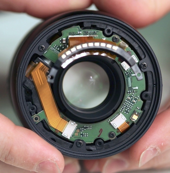
Removing the rear barrel exposes the inner barrel and PCB board. The white ring you see on around the barrel serves as a bearing to make rotation of the focus ring on the rear barrel smooth. Again, one of those "well-built" touches. It’s that smoother, tighter fit that keeps the focus ring from feeling loose and sloppy.
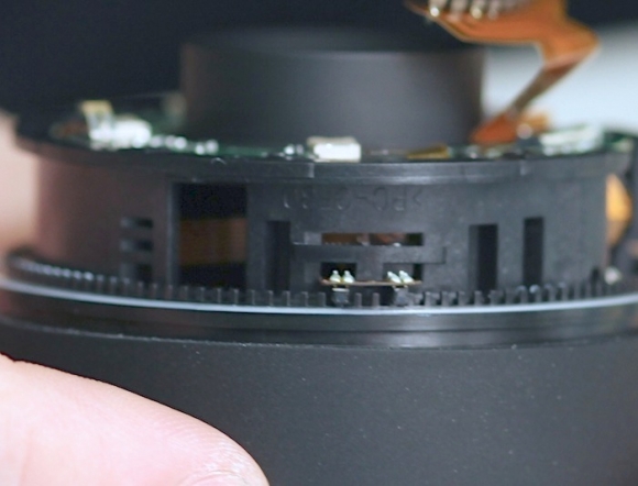
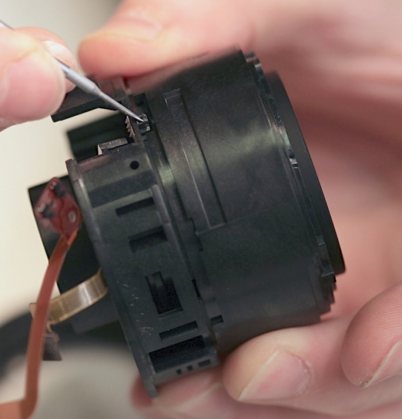
In a closer view you can see the notches along the focusing barrel and the optical position sensor it uses. (NOTE: after I published this a person more knowledgeable than myself corrected me – this is a hall sensor, not an optical sensor, but the purpose is to sense the movement of the manual focusing ring.)
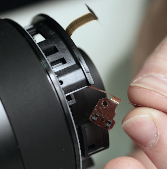
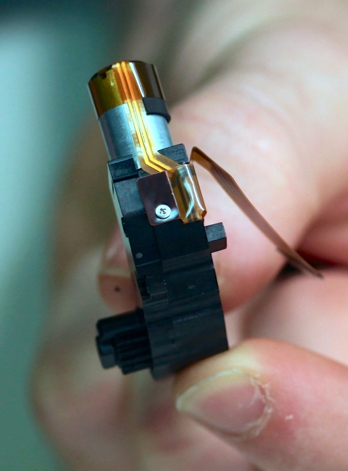
After the PCB is removed, the position sensor can also be removed.
Which lets us remove the DC motor. I will admit, when Zeiss stated they went with a DC motor because they wanted a more powerful motor to move the focusing quickly, I was skeptical (and still am, a bit) but this is quite a large motor for such a small lens. If I read Zeiss’ technical description properly, focusing involves moving the entire optical assembly in one direction and possibly the rear floating element a different amount, so a large motor probably is required.
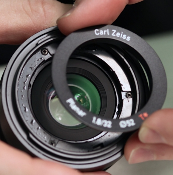
At this point it’s time to turn the lens over and start working our way in from the front. The makeup ring is removed (the liquid you see is some alcohol used to soften the glue) which exposes the screws holding the front barrel in place. Again, oversize screws with coarse threads that felt very secure.
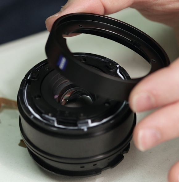
The filter ring barrel comes off after removing those three screws, and that lets us also take up the focusing ring.
These next three screws let us remove the front mounting plate. Notice how they’ve designed these thick mounting plates front and rear that accept all the attachements of the outside barrels (and therefore accept the direct stress when you drop the lens, etc.)
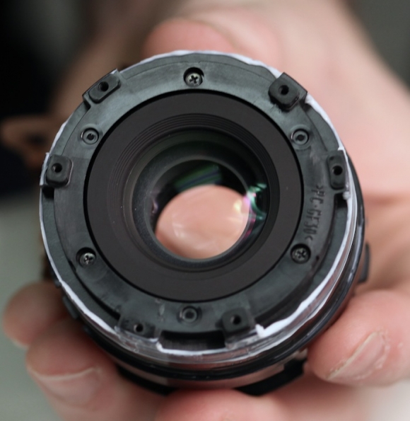
After we’ve removed this plate, the actual optics of the lens come out as a unit. So all of this dissection, layers of barrels, multiple screws, etc. are simply to handle the housing. The optics now come out in an entirely separate unit. This is quality construction.
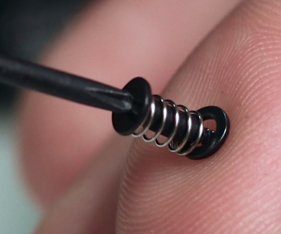
The halves of this inner housing are held together with another nice touch. Three sturdy post screws, but each screw has an associated spring and washer. If I’m understanding their purpose correctly, it should maintain even tension, broaden the area where pressure is applied, and help avoid overtightening. Like several other things we’ve seen in this lens, they could have saved a few bucks by using a simple screw and few people would ever know. I point these things out because sometimes the insides of higher-priced lenses do show us a bit about why they’re higher priced lenses.
With the innermost barrels separated you can see the aperture electronics at the bottom of the lens in the picture below. There also appears to be a second, magnetic, position sensing strip that Aaron is pointing to with the screwdriver.
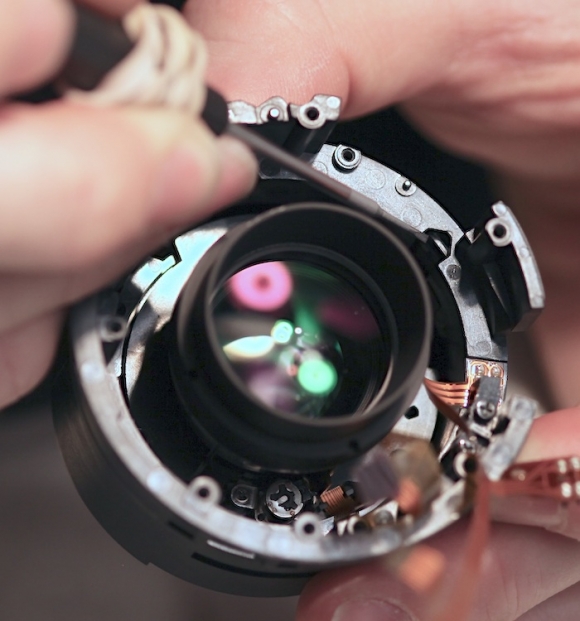
Matched to a second position sensor (again, Aaron’s screwdriver pointing to it).
I’m guessing the outer system is to sense turning of the manual focus ring for the fly-by-wire focusing system, and this one is the actual autofocus position sensor, but I could have that backwards, or just be totally wrong. With my luck this is some kind of secret-monolith tampering sensor that sent a signal to Germany the minute it was exposed to light, making sure they don’t invite me to any more lens releases.

We did not open up the optical elements for a couple of reasons. First among these was the fact that we were much more interested in the electronics and focusing system. After all this is Zeiss’ first autofocus (and for NEX electronic aperture) lens. I don’t have any question that Zeiss makes great optics but I was interested in seeing what their electronics looks like.
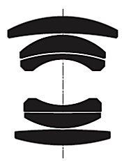
Second was the very thorough construction made it take a significant amount of time to get to this point and we have to put this back together and get to our daily repair work. Third, the 32mm Touit, like many wide-aperture lenses in this focal length, is based on a classic double-guass design with only 5 groups. There is rarely much to see or adjust within the optics of theses type of lenses and most of the elements will be cemented or solidly encased in groups.
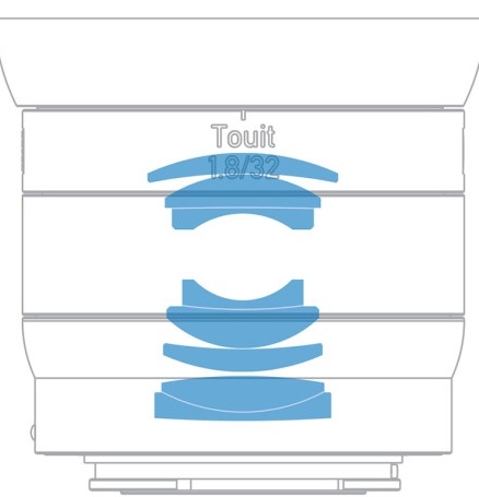
In fact, the 32mm Touit is really just an optically improved version of the ZM 50mm Planar. There are some changes in the six elements that make up the double-gauss design and the addition of a rear group, probably for aberration compensation and perhaps as a field flattener and / or floating element.
Conclusions:
This thing is built well. Those of you who have misgivings about polymer (rather than metal) construction in a lens of this size, put those to rest. It’s built like a Zeiss; I expected no less. I was a bit skeptical about the choice of a DC motor to provide more power, but I have to say, they definitely chose a large, powerful motor, so that was probably just me being cynical.
The overall construction and design were very solid, reminding me of a Zeiss or Leica rangefinder lens; much higher construction quality than many of the E mount lenses I’ve opened up.
I should point out that I have not yet opened up a Fuji-mount Touit. It will be interesting to see the differences between the two (aperture control being the most obvious). I also don’t want my remark about E mount lenses above to be carried over to Fuji. I have less experience looking inside Fuji lenses, and to be honest find them a bit strange, but they are well constructed.
(This article originally appeared on LensRentals.com. Be sure to check them out for more interesting articles, and for all your rental needs)