Testing camera performance at Imaging Resource.
By Dave Etchells
(A slightly condensed version of this article appeared as a forum post in August, 2004.)
| More about our testing |
| New Indoor/Outdoor Portrait Tests (5/23/2008) |
| New Daylight Simulator (5/23/2008) |
| "Sunlit" Portrait - What to look for (5/23/2008) |
| Indoor Portrait - What to look for (5/23/2008) |
| Still Life and Multi Targets (Updated 11/29/2010) |
| HMI Studio Lighting (5/22/2006) |
| Performance Timing (5/22/2006) |
| New Review Format (5/22/2006) |
From time to time, readers have had questions about how we manage to achieve the resolution and accuracy we do in our measurements of camera performance, specifically our measurements of shutter lag and shot to shot cycle times. I've kept putting off writing an explanation of our approach because the flood of cameras needing review have always taken precedence. While we were once taking the time to document a bit about some recent changes in our test setup (see the articles referenced in the box above right), I thought it would make sense to pull together some notes I'd jotted down in the past about our timing tests.
The basic idea of what we do is very simple in concept, it just took a little twiddling and a custom-built electronic timer to get the particular performance and characteristics we need to make the process work.
The basic idea is that you point the camera being tested at an electronic timer, and start the timer running the same instant you trip the shutter on the camera. When the shutter finally fires, the image of the timer tells you the shutter lag. The photo below shows a typical test setup. (This is another "interim" test structure, I'm in the process of building something a little neater looking, with more light thrown on the noise target in the background.)
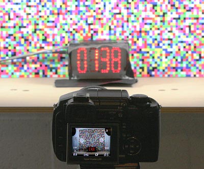
The multicolored pattern in the background is a noise pattern, designed to be very difficult for cameras' JPEG algorithms to compress. This helps us determine what a camera's worst-case buffer capacity is when making cycle-time measurements. (Many cameras' buffer capacity depends on how well the images compress as JPEGs. By presenting a background pattern that compresses very poorly, we can find and report the minimum buffer capacity.)
As I said, pretty simple, the devil is just in the details. (As always.) Specifically:
- The timer needs to count fast enough to resolve the minimum time interval desired.
- The timer needs to start the moment the shutter button is pressed.
- The camera has to be using a fast enough shutter speed to freeze the digits to whatever time resolution you need.
- The digits of the timer need to be bright enough to register on the image sensor at that short a shutter speed.
- The rise and fall times (turn on/turn off times) of the segments of the timer digits need to be fast enough to not blur the digits over the time scale of the minimum time resolution desired.
- The refresh rate of the timer digits (if multiplexed) has to be several times that of the minimum time resolution.
- And of course, the timer needs an accurate, stable time base.
A full discussion of all these issues is beyond the reach of this article, but here are a few notes about the setup I use:
- The timer I built counts at either 100 or 1000 counts/second, selected via a toggle switch. Resolution can thus be as high as either 1/100 or 1/1000 second, depending on the switch setting. (But see the note below about shutter speed.)
- I start the timer at the same moment as the camera shutter is tripped by the simple expedient of pressing the camera's shutter button (very sharply) with a pushbutton switch that itself starts the timer. This sounds simplistic, but has actually proven to be surprisingly accurate. Without going into all the gory details, even if you assume that the the timer's pushbutton and camera's shutter button require very different pressure levels for actuation, a simple calculation involving the velocity of the pushbutton as it approaches the shutter button, and the relatively short distance the two buttons have to move to close their respective contacts gives a timing uncertainty of under a millisecond.
- On cameras with manual modes, I set the shutter speed at 1/1000 or 1/1,250, to give a resolution of 0.001 sec. For cameras with no manual shutter control, I use very strong lighting, to force their shutter time down to 1/1000 or less. (The camera's max shutter speed permitting, of course.)
- One of the reasons I had to build custom hardware was to get the display digits bright enough. Each segment of the display uses three 3000 mcd discrete LEDs. This gives enough light for the digits to be visible at 1/1000 and ISO 100, at something around f/4 or so. (Obviously better if the camera has ISO 400 or above, but it'll work even at ISO 100.)
- Segment rise and fall time is another reason I had to go with custom hardware. LCD displays (as are used on commercial stopwatches) have relatively slow rise and fall times. Trying to photograph the hundredths-of-seconds digit while an LCD timer is running will produce only a blur, with the digit(s) reading "88". This is because the LCDs relax too slowly to return to their "off" state between counts, even at time scales on the order of a tenth of a second. In constructing the timer shown here, it was a real pain getting the rise and fall times short enough to avoid blur from the high multiplex rate on the display, but the end result works pretty well.
- Display-multiplex rate is another reason for custom hardware. The multiplexing rate on the digits of my counter is ~7 kHz, fast enough that all digits are scanned multiple times, even on an exposure as short as a thousandth of a second. (I could have made the design simpler by not multiplexing, but at considerable cost in parts count.) On the "someday" project list though, is a timer version built around a number of low-end microcontroller chips, that will have non-multiplexed digits.)
- To provide accuracy and stability, I used a crystal-controlled time base, thereby avoiding thermal drift as the electronics warmed up or cooled down.
The bottom line is the setup works surprisingly well. I've successfully and very repeatably measured the prefocus shutter lag on the Sony F828 at only 9 milliseconds (0.009 second), exactly matching Sony's spec for the camera. As further evidence, a site reader with a special application tapped into the F828's innards to access the shutter button contacts directly, and measured exactly the same shutter lag as I did. - So I'm pretty confident in my claim of 0.001 second resolution and accuracy.
Just for fun, here are a few views of the guts of the timer I built for this project:
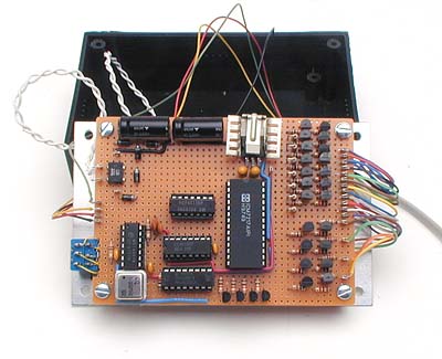
Here's a top-side view of the perfboard I built it on. This was a one-off project, so it wasn't worth the investment of making a printed circuit for it. The main display-driver IC is a now-obsolete Intersil 7217 4-digit counter chip. (You can bet I bought a couple of spares, in case the chip dies at some point!) It didn't have quite enough drive at its outputs to handle the sets of three high-intensity LEDs that make up each segment, so I added driver circuitry built from discrete transistors. This turned out to be the messiest part of the design, as I had a hard time getting the high-current drivers to turn on and off quickly enough to avoid smearing the digits.
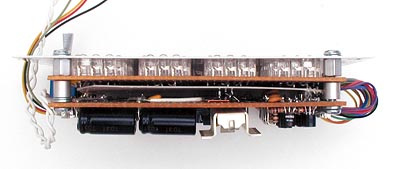
Here's a side view. the timer is actually composed of two circuit boards. One holds the circuitry seen above, the other holds the 86 LEDs that make up the digits and two decimal points. I flipped the display board back to back with the main circuit board, and ran the multiplexed signals between the two boards via a dozen or so pieces of stranded wire. The other spidery-looking wires are from a length of modular phone cable, and carry the signals to the remote switches that operate the timer. One switch starts and stops the timing, the other clears the digits. The remote switch assembly can be stretched to operate as far as 30 feet away from the timer, for testing cameras with very long telephotos at a reasonable focal distance.
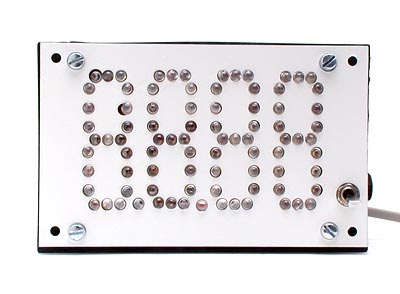
Here's the timer face, an array of 86 holes drilled in a plate of aluminum, for the LEDs to poke through. (Sure wish I had a CNC drill for this sort of thing, the results of a couple of minor bobbles I made while drilling the holes are painfully obvious in this close-up, and the whole thing looks a little funky.)
So that's how we test shutter lag and cycle times here at IR, and a look at the little circuit I cobbled together provide the timebase for it. It isn't exactly beautiful, but it does an excellent job of collecting the data we need.