INSIDE Image Stabilization: Olympus takes us on a geek’s tour of what makes IS work
posted Wednesday, July 29, 2020 at 6:49 PM EDT
The rise of image stabilization has brought with it more benefits for photographers than just about any other technology, and in recent years it's been getting really good. I've wanted for a while now to make an explainer article and video that would give users a behind-the-scenes look at how that's been achieved... and the time has finally come!
Image stabilization solves a problem that most photographers have experienced, amateurs and pros alike. At some point we've all handheld shots in low light only to be disappointed by blurry results from camera shake. Image stabilization gives our handholding game a shot in the arm, allowing crisp results at way, waaay slower shutter speeds than we could manage on our own.
Image Stabilization: The Basics
There are two main types of image stabilization: in-body image stabilization (often abbreviated to IBIS) or optical image stabilization (aka in-lens or lens-based IS). Each works to correct the fundamental problem caused by camera shake -- the image projected by the lens moving across the sensor surface during exposure. (There's also something called electronic or digital image stabilization, based on simply shifting the location of data readout on the face of the sensor. Electronic image stabilization can introduce motion artifacts that IBIS and lens-based IS avoids.)
Lens-based IS first appeared in the heyday of film in the mid-1990s, and sensor-shift IS followed even before digital reached its peak in the mid-2000s. Optical stabilization moves a floating lens element to shift the optical path slightly, countering motion from camera shake, while in-body stabilization instead moves the sensor itself so the image remains centered on the subject.
The effectiveness of a specific IS system can be represented in stops or EV steps, with a one stop improvement meaning a factor of two improvement in the longest handholdable shutter speed. For example, if you could handhold a shutter speed of 1/200th second at a certain focal length without assistance, a one-stop improvement would allow handholding a 1/100th second exposure, two stops would allow 1/50th second, and so on.

Going deep with the stabilization champs
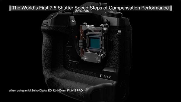
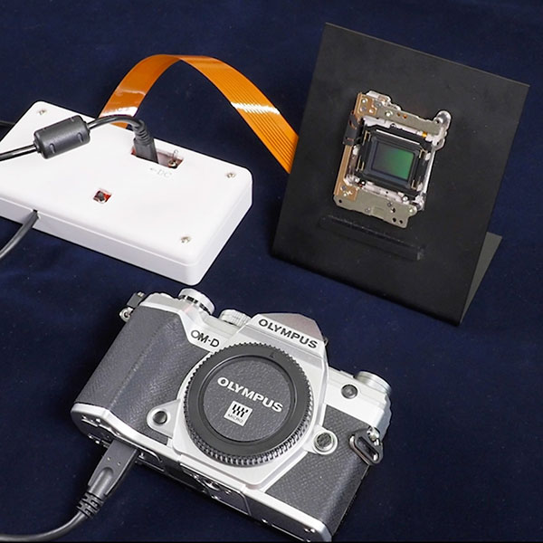
Olympus has some of the best image stabilization technology in the photo business. Their flagship Olympus OM-D E-M1X mirrorless camera, in particular, debuted a seriously impressive 7.0 stops of in-body stabilization. (And a combined 7.5 stops if paired with the M.Zuiko Digital ED 12-100mm F4.0 IS PRO lens.) That same technology is now available in their E-M1 Mark III, bringing amazing IS performance within reach of advanced amateurs, and in a more compact body to boot. Given their top-tier performance and deep experience, Olympus was the first company that came to mind when I went looking for someone to take myself and our readers on a deep dive of IS tech. When I approached them about sponsoring the project, they jumped at the chance, and invited me to come by their R&D headquarters the next time I was in Japan.
So it was that I found myself riding the Tokyo Metro Chuo line to Olympus' R&D HQ in Hachiochi, Japan, and talking image stabilization with Hisashi Takeuchi, the General Manager of the Mechatronics Technology Department in Olympus Corp.'s Imaging Product Development Division. Takeuchi-san's department is responsible for both in-body and in-lens image stabilization systems, so was the person to not only to discuss both technologies in general, but also take us inside their cameras and lenses and really show us the nuts and bolts of both systems.
A Rich History of Both In-Body and In-Lens Stabilization
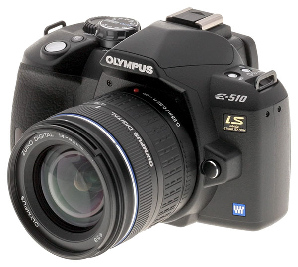
Olympus' first mechanically-stabilized camera was the fixed-lens CAMEDIA C-2100 Ultra Zoom, released in mid-2000 with in-lens image stabilization. The company followed with its first use of in-body stabilization in 2007's Olympus E-510, one of its interchangeable-lens Four Thirds lineup.
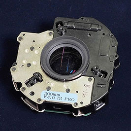
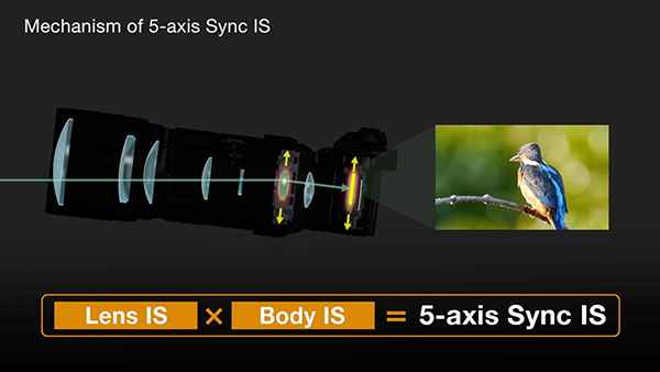
In 2012, the E-M5 upped the ante with Olympus' first five-axis IBIS system. And by 2016, it was not only offering in-lens stabilization for the first time, courtesy of the M.ZUIKO ED 300mm f4.0 IS PRO lens, but also a world's first with its Sync IS system. Available with the E-M1, E-M5 II and PEN-F camera bodies, Sync IS allowed the in-lens and in-body IS systems to work together for even better stabilization.
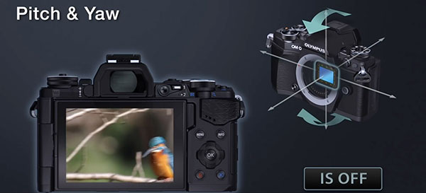
Given that most camera makers started with lens-based IS and eventually moved to a body-based approach, I was curious why Olympus chose the opposite approach. According to Takeuchi-san, the answer is that they were already thinking towards a five-axis future, with the added axes of stabilization making their systems effective in more situations than is possible with lens-based stabilization alone. He also clarified that the addition of horizontal/vertical shift is most helpful for shooting macros, with pitch, yaw and roll alone being sufficient for most wide-angle and telephoto shooting.
The Incredible Evolution of IBIS
It's incredible to me just how far image stabilization has come in the just over a decade since the launch of the E-510. Back then, a three-stop correction was considered pretty good for any sort of an image stabilization system. Returning to my previous example, that would let you hand-hold shots at 1/25th second, if a slowest shutter speed of 1/200th second was the best you could do by yourself without blurring the image.
These days, a system like the one in the E-M1X (the current record-holder) are capable of 7.5 stops, and even affordable enthusiast-grade cameras can manage 5.5 stops with the body alone. Going back to our example, a 5.5-stop correction would let you capture sharp images at 1/4 second instead of 1/200th, and 7.5 stops would allow handheld exposures of longer than a second. (!!)
How Image Stabilization Went From Great to Mindblowing
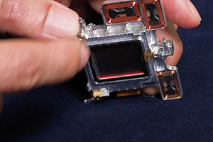
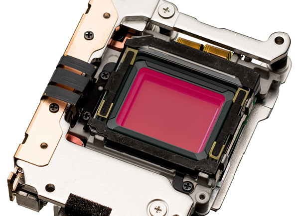
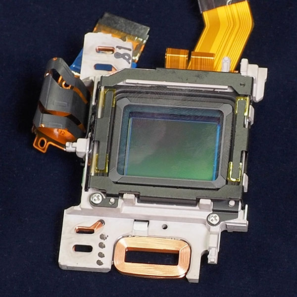
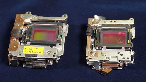
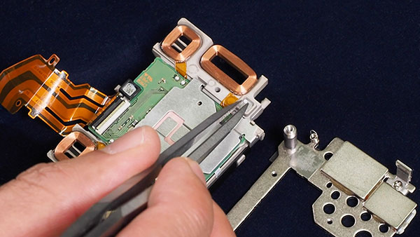
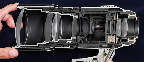
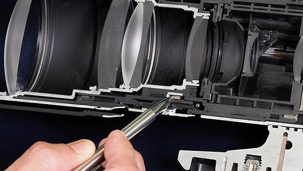
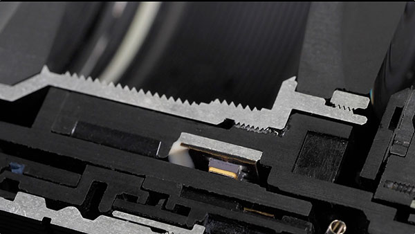
During our meeting, Takeuchi-san showed me cutaways of the E-M1 II and E-M1X cameras and the 300mm f/4 lens, and image stabilization hardware which had been entirely removed from the camera and partially dismantled. This gave me a first-ever opportunity to see how the systems functioned, and also to see how the improvements made over the years had led to incredibly compact IBIS systems like the one in the E-M5 III. The size reductions alone were impressive, even without considering the higher performance of modern systems.
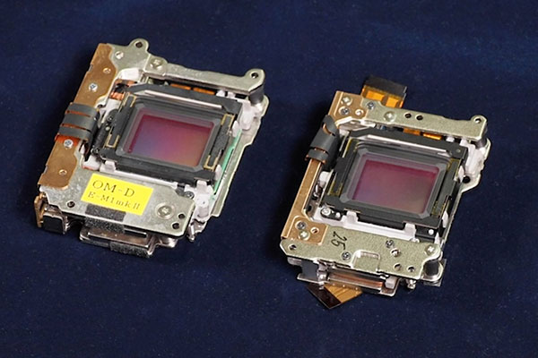
Comparing the image stabilization assemblies of the E-M5 III and the system in the E-M1 II -- a model from just three years earlier with equivalent stabilization performance -- I learned that Olympus had reduced the volume by around 15%, and the weight by fully one-quarter. To achieve this, Olympus removed the electromagnetic coils from their own separate base plate and instead placed them in cutouts in the sensor carrier plate itself, reducing the overall assembly thickness. The differences were even more stark when comparing the E-M5 III's modern, five-axis IBIS system and its free-floating sensor against the rail-guided, dual-axis system of the 13-year old E-510. My degrees are in electrical engineering vs mechanical, but I was amazed that the E-M5 III's sensor could seem to float so freely, while still maintaining the micron-level alignment with the lens that's required.
Gyroscopes and accelerometers
As I was writing this, I realized I was about to blithely use the term "gyros", and that many people might not understand what that was all about.
There are two ways that a camera can move to blur an image: Rotation or translation. Rotation is self-explanatory, while translation just means moving up or down, left or right without rotating. To be able to counteract such motion, an image stabilization system needs two types of sensor, one for each type of motion. Rotation of the camera is the main cause of blur in most types of photos, but translation can be a problem in macro shots as well.
Devices that react to rotation are called gyroscopes or gyros for short. Chances are you've seen a toy gyroscope at some point or another in a general science or physics class: A rapidly spinning rotor inside a stationary cage makes the gyroscope resist rotational movement. You can set a gyroscope tilted at an angle on a support, and it won't fall down. Instead, it will slowly revolve around the support point, floating almost as if by magic. If you've ever held one in your hand while it was spinning, you'll know the surprising and eerie way it resists being turned.
Microelectronic gyro sensors don't have spinning discs inside them, but instead use microscopic vibrating parts to detect rotation. They're based on the same underlying principle though, and can detect incredibly small amounts of rotation.
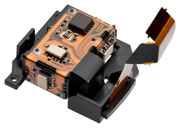
As the name suggests, an accelerometer is a device that detects acceleration. It measures acceleration rather than position, but by looking at acceleration over time, you can tell what the position of the device is. The IS system can use this information to correct for translational movements.
Interestingly, we have automobile airbags to thank for the microelectronic mechanical systems (MEMS) technology that's led microchip accelerometers and gyros. Car makers needed millions of very reliable, dirt-cheap accelerometers to trigger airbags in the event of a crash, and that need drove the development of MEMS technology. Photographers are beneficiaries of the technology paid for by hundreds of millions of cars on the road :-)
How did Olympus get such good gyros?
I asked Takeuchi-san how it was that Olympus achieved such a dramatic step up in stabilization ability, and why other manufacturers haven't managed to reach that level yet. The answer surprised me: Olympus worked closely with Seiko Epson Corporation (their supplier for gyro chips) to jointly develop a gyro with performance an order of magnitude (a factor of 10) better than what had gone before. It surprised me that a camera manufacturer like Olympus would get so deeply involved in developing the components they use, but it seems to have paid off handsomely for them in this case. With three of the new-generation gyros paired with an accelerometer in the E-M1X, the system improved by a full stop in stabilization accuracy over what was possible with the best previously-available gyros.
I said "accuracy" there, although it doesn't give a good sense of just what the improvement was. When it comes to photographic image stabilization, the critical issue ends up being how long the gyro can keep its output perfectly stable for.
MEMS gyros inevitably produce a small signal or "bias" when they're perfectly stationary; they're basically saying that they're rotating slightly even when they're standing still. The stabilization system just subtracts this bias out in software, but the value drifts slowly over time. This "bias drift" may not be very large, but then again, it takes only an extremely small change in angle to shift the image by a pixel or more, resulting in a blurry photo. As we've discussed above, a 7.5 stop IS system needs to hold things steady for up to a couple of seconds.
Think about that again: The gyro has to be so stable that it can distinguish between its bias drift and rotations so slight that they correspond to less than a single pixel of image movement on the surface of the sensor, across several seconds. For a 24 megapixel camera with a 50mm-equivalent lens, one pixel corresponds to about 6 thousandths of a degree. How small is that? For our US readers, think of a 10 foot long straight edge, resting perfectly level. Now put three sheets of copier paper under one end. Thats 0.006 degrees. (For our readers in metric countries, think of a meter stick and put one sheet of paper under the far end.) That's how little movement the gyro has to be able to detect, over one to two seconds.
Here's another way of looking at it: If you were constantly turning at a rate of 0.006 degrees every 1.5 seconds or so, it would take you 25 hours to turn in a full circle (360 degrees)!
Deep Dive: How Image Stabilization Works
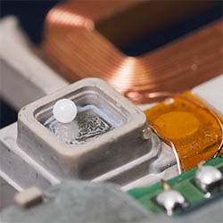
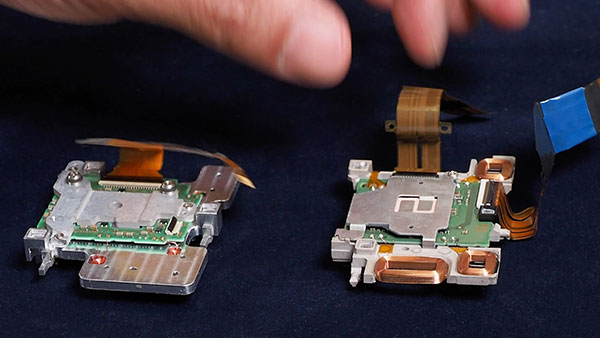
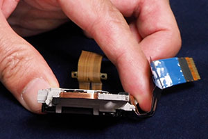
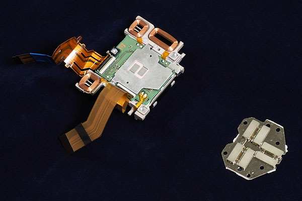
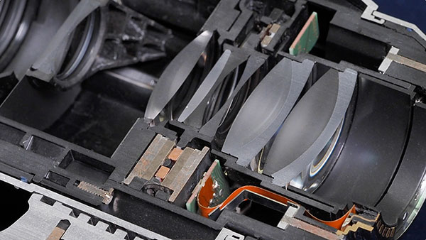
Among the unique opportunities I had during my visit with Takeuchi-san, one of the coolest for an engineering nerd like myself was the chance to see and handle the partially-disassembled sensor shift components for myself. It's much easier to get a sense for how everything works when you can see all the component parts in detail.
Voice-coil motors
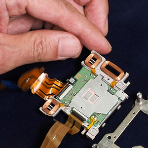
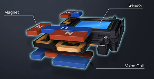
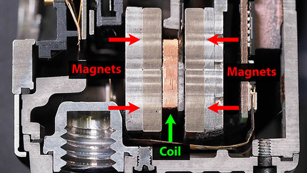
At their most fundamental, the way in which modern IBIS systems work is still very much like those in the early days, just with greater precision and sophistication. A number of permanent magnets arranged in pairs on the fixed portion of the sensor-shift assembly interact with electromagnetic forces generated by coils attached to the floating sensor carrier plate.
These are what's known as voice coils, and together with the magnets positioned above and below them they form voice-coil motors, so named because loudspeakers, headphones and the like use the same sort of mechanism to turn electricity into sound vibrations. Running an electrical current through a coil of wire creates a magnetic field that will push or pull against a nearby permanent magnet depending on the polarity and amount of current flowing.
In a camera or lens, the force generated by the voice coil motors lets the IS system move the sensor or lens element in very small, precisely controlled increments.

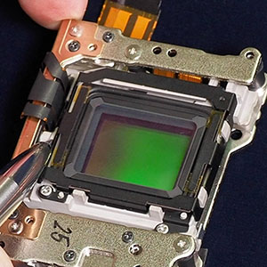
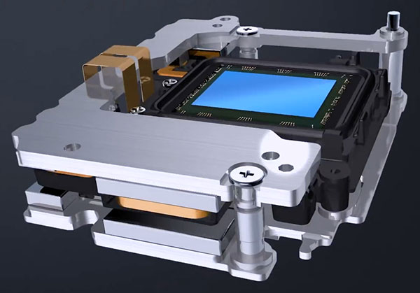
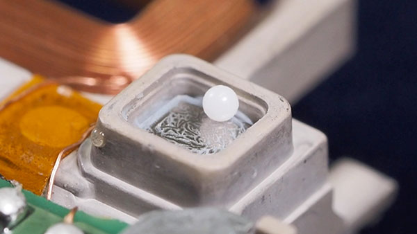
Ensuring that it stays perfectly level and perpendicular to the central axis of the lens, the seemingly floating carrier plate actually glides on tiny ceramic bearings less than a millimeter in diameter. The bearings and the surfaces they ride on are so smooth that the whole sensor frame stays flat to within a few thousandths of a millimeter, regardless of its X-Y position. (Again, I'm no mechanical engineer, but I was amazed that the sensor could move so freely, yet stay so precisely aligned.)
Three coils, five axes
Just three voice coils are needed for a five-axis IS system like that in the E-M5 III, with each coil riding between a pair of permanent magnets. Tilting the camera up or down, right or left (pitch and yaw rotation) produces the same X/Y motion of the image on the sensor's surface as you'd get from shifting it in those directions without rotating it. So just being able to move the sensor in two directions gives you four "axes" of correction. (The earliest systems only corrected for pitch and yaw, not up/down/left/right motion, because they had only gyro sensors, not accelerometers as well. So while their x/y sensor motion could correct for both types of movement, they didn't have the sensors to detect linear translation.)
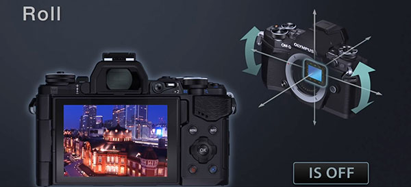
The remaining axis refers to rotation around the lens, or "roll". This can happen when shooting still images when you mash down the shutter button quickly, making the right side of the camera drop slightly. Even if you're careful with the shutter release though, it's pretty hard to hold the camera perfectly level during a long exposure, and this kind of rotation can be very visible when you're handholding video.
A five-axis IS system compensates for roll rotation by rotating the image sensor within the camera body. Olympus does this by playing the voice coil motors off against each other. Each pair of coils moves the sensor back and forth or up and down when they act together. If the current in the coils is unequal, though, it will produce a twisting force on the sensor, making it rotate relative to the fixed base.
It's important to note that this is a critical advantage of body-based IS systems; they're able to compensate for roll rotation, whereas lens-based systems cannot. This is because lens elements are radially symmetric. That's a fancy way of saying that a lens will bend the light the same, regardless of how you might turn it around its optical axis. If you take any element in a photographic lens and spin it 90 degrees in its mount, the image will look exactly the same. (Unless you're really bad at making lenses.) ;-)
Takeuchi-san explained that this was a key reason that they chose to pursue body-based image stabilization from the very beginning. They knew that lens-based IS couldn't compensate for every kind of camera movement, so wanted to develop a body-based approach to handle those situations as well.
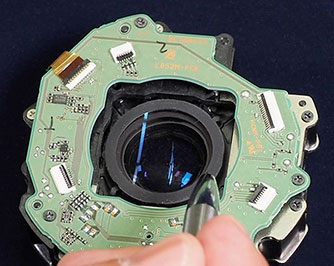
How does the system know how much the sensor has moved?
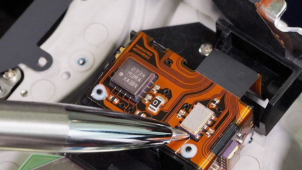
The sensor position has to be controlled so precisely (to within just a few thousandths of a millimeter) that it's impossible to just send "x" amount of current through the voice coils and expect the sensor to move exactly the right amount. The system uses what's called a Hall-effect sensor to measure the sensor position with incredible accuracy. This is a semiconductor chip that's positioned next to yet another set of magnets, measuring the magnetic field as a way of determining the position. I won't go into the details of what Hall-effect sensors are all about, you can read Wikipedia for that. Suffice it to say that they're capable of very rapid, accurate measurements of sensor position.
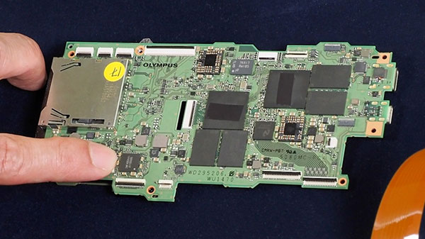
Controlling an electromechanical system so precisely in real time is tricky though, requiring a lot of calculations to figure out where the sensor is, how fast it's moving in what direction, how hard it needs to be pushed to either move more in that direction or even change directions, etc, etc. Olympus cameras have two high-speed CPUs devoted to deciding how much current to send to the voice coil motors, moment by moment.
Lens-based IS came first, but in some respects IBIS beats it
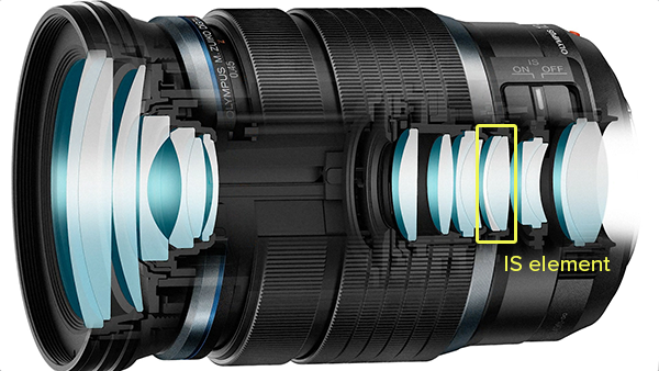
Back in the film camera era, lens-based image stabilization was the only kind available. Lens-based IS systems operate quite similarly to in-body image stabilizations in some respects, and again function using voice-coil motors. Instead of moving the image sensor, though, they instead shift a lens element or group of elements.
These movements of the lens element(s) will in turn skew the optical path so as to counteract camera shake, shifting the light rays as they pass through the element without otherwise affecting their point of focus or optical alignment. Of course, as we've already discussed lens-based IS can't correct for rotational motion, and so in-body image stabilization has an edge in that respect. Body-based IS also tends to be more capable at wide angle focal lengths, while lens-based IS can provide more correction range at the telephoto end of things, but the most fundamental difference between the two approaches is that body-based is able to compensate for rotational motion.

Although their cameras already have gyros in their bodies for the sensor-shift IS, Olympus still needs to include gyros in their IS-capable lenses as well. The data connections between the body and lens aren't fast enough to correct for camera shake in real time, without introducing unacceptable lag.
The Holy Grail of IS Yields the Ultimate Performance
If you've stuck with me this long, you'll probably already be wondering about the next question: Can in-body and in-lens stabilization systems work together? Could you get even better IS performance just by attaching an IS lens to an IS-capable body?
It turns out the answer isn't as simple as it might seem. If you think about it, the lens and the body IS systems would both be trying to do the same thing. Unless they coordinate with each other, the body-based IS would try to correct for the camera motion it saw, but the lens would already have corrected for it. The net result would be blur just as bad as you started with, but in the opposite direction!

In-body and in-lens stabilization working together was the holy grail of IS technology for years, and Olympus accomplished it with their Sync IS technology. Just as you'd expect, the lens and body-based IS work together, so the overall system can compensate for more motion than either side could by itself. This helps in still photography, and you can see an improvement of anywhere from 0.5 - 1.0 EV with compatible Olympus cameras when working in concert with a lens' IS system, vs the bodies working by themselves. (The precise figure for Sync IS' improvement varies by camera model.)
The impact on video recording can be much more pronounced, though. Recall that the ultimate limit of IS performance has more to do with the bias drift of the gyro chips than anything else. With video, though, the limiting factor is how much total camera motion the IS system can compensate for before running out of compensating ability. It can be a tricky balance, deciding how you handle large amounts of motion, so you can keep things stable for as long as possible, without getting large "jerks" when the system runs out of room with its compensation elements.
It's very much been my experience though, that the benefits of Sync IS are most obvious when shooting handheld video, especially if I'm panning or (horrors) walking with the camera. It's a very significant difference, and of course, the added stop or so of improvement on still shots is welcome too.
And of course, as an added bonus, Sync IS includes the ability of body-based IS to compensate for rotation along the roll axis as well.
The Future of Stabilization: Even Smaller and Better
As I said at the outset, we've seen enormous improvements in image stabilization over the past decade or two, and especially in the last few years. With such a great improvements already made, I found myself wondering where Olympus might see further opportunities for improvement in the future. When I asked him, Takeuchi-san's said that with the effectiveness of stabilization systems now reaching such a high level, the main focus is in the future will be on making the technology even smaller and lighter. Looking at the change between the system from the now-ancient EVOLT 510 and that in the current E-M5 III, it's hard to imagine how they'd manage to shave even more from the size and bulk. Given Olympus' focus on compact size and light weight in their Micro Four Thirds cameras, though, it's clear that this will be an important focus going forwards.
Summary: Got Any Questions? Let Me Know...
As I said at the outset, my main goal here was to explain a bit about how IS systems work in general, and share some of my amazement at how sophisticated the technology has become. Let me know how I did on that score in the comments below, and feel free to ask any questions you might have; I'll monitor the comments here for at least a week or two after posting. I can't guarantee that I'll have all the answers, but I'll be happy to bring any deeper questions I can't answer back to the Olympus R&D engineers and let you know what they say! (Of course, be prepared for "we can't comment on that", if the question touches on proprietary information. I get a lot of that from all the camera manufacturers when probing myself ;-)
COVID-19 note: While this article is being published in late July, 2020, the interviews, photos and videos were all conducted in Hachioji, Japan in late October, 2019 before the crisis began.